
How Do I Test a Fuel Gauge: Simple Steps and Accurate Diagnostics
How do I test a fuel gauge? Start by using a multimeter to check if the gauge receives a steady 12 volts at its positive terminal. If voltage is present but the gauge doesn’t respond, test the fuel sending unit’s resistance and wiring next. This method isolates whether the issue is in the gauge, sending unit, or electrical connections.
Key Takeaways
- Confirm the fuel gauge positive terminal has 12 volts using a multimeter before testing other components.
- Measure the fuel sending unit resistance; typical calibration for empty is around 73 ohms and full around 10 ohms.
- Check the signal wire resistance between the sending unit center stud and the gauge plug to locate wiring faults.
- Verify the constant voltage regulator output; it should convert 12 volts to approximately 5 volts for the fuel gauge.
- Inspect ground connections thoroughly, as poor grounding often causes inaccurate or fluctuating gauge readings.
- Use the ignition ON/ACC position to test voltage inputs for consistency between 12 and 13 volts at gauges.
How to Test a Fuel Gauge Using a Multimeter
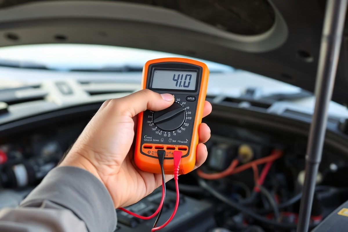
Testing a fuel gauge with a multimeter involves checking the voltage supply to the gauge, measuring the resistance of the sending unit, and confirming the grounding of the signal wire. These steps verify the circuit’s functionality and help pinpoint failures. You’ll need a digital multimeter set to the correct mode, your vehicle ignition in the ON position, and basic knowledge of your fuel gauge wiring.
Checking Power Supply Voltage
Start by confirming the fuel gauge receives proper power. The gauge operates on a 12-volt supply, typically from the ignition circuit, which powers the gauge when the key is in the ON or ACC position. Verifying this voltage ensures the gauge has the necessary input to function correctly.
Use your multimeter set to the DC voltage range to measure between the fuel gauge’s positive terminal and a good chassis ground. Expect a steady reading near 12 volts if the circuit and ignition switch are working correctly. A significantly lower or fluctuating voltage suggests wiring issues or a faulty ignition source.
Measuring Sending Unit Resistance
Next, assess the resistance of the sending unit on the fuel tank. The sending unit varies resistance based on fuel level, causing the gauge to change its reading. Typical resistance values range from about 73 ohms when empty to roughly 10 ohms when full. Use the ohms setting on your multimeter, preferably set to a 200-ohm scale, for accuracy. Follow these steps to measure resistance at the sending unit terminals:
- Locate the sending unit terminals on the fuel tank; identify the signal wire and ground wire.
- Turn the vehicle ignition OFF to avoid any electrical hazards.
- Set the multimeter to measure resistance (ohms). Use the 200-ohm range for precision.
- Attach the multimeter leads to the signal terminal and ground terminal on the sending unit.
- Manually move the float arm to the full position; note the resistance reading, which should be near 10 ohms.
- Lower the float arm to the empty position; the reading should rise to about 73 ohms.
Resistance readings significantly outside these ranges indicate a faulty sending unit that may need replacement or calibration.
Testing Signal Wire Grounding
The fuel gauge interprets fuel level by reading variable resistance to ground through the sending unit. To test the gauge’s ability to respond correctly, you can simulate a grounded sending unit signal wire, which should cause the gauge needle to move to “full.” Follow these steps cautiously:
- Turn ignition to the ON/ACC position to power the gauge.
- Identify the signal wire leading from the sending unit to the fuel gauge.
- Using an insulated jumper wire or a screwdriver with an insulated handle, carefully ground the signal wire near the gauge to chassis ground.
- Observe the fuel gauge needle; it should deflect toward the full position as the signal wire is grounded.
- Remove the ground connection after the test to avoid damage to the system.
Movement of the gauge needle confirms the gauge and wiring respond properly to changes in the signal wire ground. No movement may indicate a bad gauge or wiring fault.
Interpreting Multimeter Readings
Reading and understanding your multimeter results ensures accurate diagnosis. Fuel sending units usually show about 73 ohms at empty and 10 ohms at full, but some units may vary slightly, ranging from 90 ohms empty to 0 ohms full. A reading near zero ohms with the float down typically means empty, while higher resistance corresponds to less fuel.
Voltage readings at the fuel gauge positive terminal should be consistently close to 12 volts with ignition ON. Resistance between the ground wire on the sending unit and chassis should be near zero ohms to ensure proper grounding. High resistance or no continuity suggests poor ground connections.
Results that deviate from these norms point to potential issues: sending unit damage, wiring breaks, poor ground, or a faulty gauge. Testing multiple points gives a full picture and can isolate the malfunction quickly before costly replacements.
Understanding How a Fuel Gauge System Works
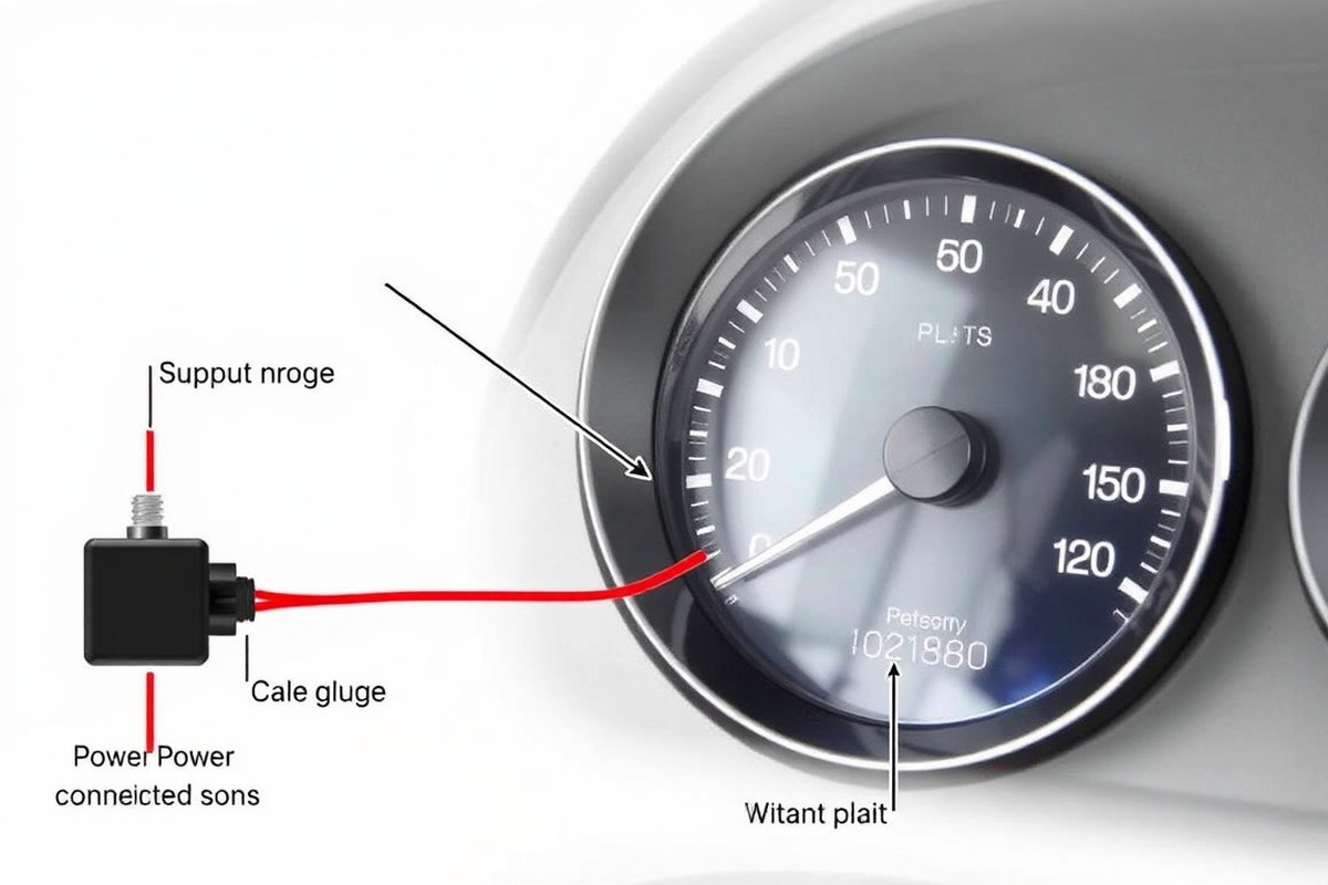
The fuel gauge system relies on a combination of parts working together to show you how much gasoline is in your tank. The key components include the fuel level sending unit inside the tank, the electrical wiring that transmits signals, the instrument cluster gauge on your dashboard, and the voltage stabilizer that keeps readings steady. The most critical part is the sending unit, which uses a float attached to a metal arm that moves up and down with the fuel level.
Inside the sending unit, there is a rheostat, a variable resistor connected to the float arm. As the fuel level changes, the float moves, and the rheostat alters the electrical resistance it sends to the instrument cluster. When the tank is full, the resistance is at one end of a set range, and as the fuel level drops, the resistance value changes accordingly. This variation in resistance is what the fuel gauge interprets and displays as a fuel level.
The instrument cluster receives the changing resistance signal, converting it into a needle movement or digital readout. A voltage stabilizer inside the cluster ensures that voltage fluctuations from the vehicle’s electrical system don’t distort the gauge reading. Calibration plays a role here: after installing a new sending unit or gauge, you need to adjust the fuel gauge’s “Zero” setting to match the sending unit’s resistance range, often a value between about 10 ohms (empty) and 73 ohms (full), depending on your vehicle. Proper calibration ensures the gauge shows accurate readings at every tank level.
Problems can arise if the float loses buoyancy or the rheostat wears out, causing inaccurate resistance signals. A worn rheostat might develop dead spots where the electrical contact fails intermittently. This leads to erratic or stuck readings on the gauge, even if the float physically moves with the fuel. Similarly, if the electrical wiring or ground connections to the sending unit are loose or corroded, the signal might weaken or fail entirely.
Matching the sending unit and gauge to each other is important because they are designed to work within a specific resistance range. Replacing one without the other can cause further inaccuracies. To avoid surprises, bench testing the sending unit and gauge before installation verifies they respond correctly across the resistance range. This saves time and money by ensuring you only install functional parts that work well together.
Always calibrate the fuel gauge’s zero adjustment lever after installing a new sending unit to ensure accurate fuel level readings on your dashboard.
Common Causes of Fuel Gauge Failure and Their Symptoms
Fuel gauge problems often stem from three main areas: the fuel sending unit, wiring or grounding issues, and failures within the instrument cluster itself. Understanding the typical failure points and recognizing their symptoms can help pinpoint the root cause more efficiently, saving you time and money on repairs.
The fuel sending unit is located inside the gas tank and measures the fuel level via a float and variable resistor. It can wear out or stick, causing the gauge to read full, empty, or jump erratically. A bad sending unit usually results in a gauge that doesn’t move at all or stays fixed on one level regardless of fuel changes. Since replacing a sending unit costs between $50 and $200 for the part alone, plus labor, you want to be sure this part is the issue before proceeding.
Wiring problems, such as a bad ground connection or corroded connectors, often create the same symptoms as a faulty fuel sending unit. Watch for inconsistent or shaky gauge behavior, or a gauge that only works when you manipulate wires or connectors. Ground wires can be found near the sending unit on the tank, behind the gauge, or along the passenger-side rear frame rail. A quick way to check is to inspect connectors for corrosion and test continuity with a multimeter. When the ground is bad, restoring a solid connection can immediately fix the reading.
- Fuel gauge stuck at full, empty, or one level despite fuel changes
- Erratic or jumping fuel gauge needle
- Gauge unresponsive or slow to update after refueling
- Fuel gauge works only when tapping or adjusting wiring
- Cluster needle movement without corresponding fuel level change
- Burnt smell or visible damage behind the instrument cluster
Fuel gauge failures caused by the instrument cluster circuit board are a common complaint, especially in vehicles with electronic digital clusters, like certain GM trucks and SUVs experiencing stepper motor failure. This situation shows a gauge that remains unresponsive even though the sending unit and wiring are good. Testing for 12 volts at the gauge is a key step; if power is present but the gauge fails to move, the cluster or gauge mechanism itself is often to blame.
To tell if the sending unit or gauge is bad, locate the sending unit connector on top of the fuel tank. Testing resistance with a multimeter in the sending unit’s upright position helps identify faults. Resistance stuck at one value, out of the manufacturer’s expected range, or reading open/infinite indicates a faulty sending unit. When the sending unit tests fine but the gauge doesn’t respond, focus on wiring and cluster testing next.
How to Test Fuel Sending Units: Resistance and Float Checks
Testing a fuel sending unit involves measuring its electrical resistance at different float positions to ensure it sends correct signals to the fuel gauge. You check resistance values with a multimeter while moving the float arm from empty to full positions. Detecting steady resistance changes confirms the sender’s condition, while erratic or stuck readings reveal problems like dead spots or mechanical faults.
Setting Up the Multimeter for Resistance
Begin by preparing your multimeter for an ohms measurement. Choose an ohm range appropriate for the sender’s resistance, typically under 100 ohms, to get precise readings. Connect the multimeter probes to the sending unit terminals, ensuring solid contact without bending or stressing wires.
Position the sender upright so the float arm can move freely without obstruction. This setup prevents false readings caused by restricted float movement or poor connections.
- Select the multimeter’s resistance (ohm) setting, typically the lowest range that can measure from 0 to around 20 ohms.
- Place the sending unit securely on a bench or stable surface in a vertical position.
- Attach the multimeter probes firmly to the two terminals of the fuel sender.
- Verify the probes contact the metal terminals only, avoiding contact with each other.
- Ensure the float arm is free to move and doesn’t catch on any parts.
Measuring Resistance at Empty and Full Positions
Test resistance at the two critical float arm positions: fully lowered (simulating empty tank) and fully raised (simulating full tank). Record these values to compare with typical ranges for proper operation. For many senders, an empty position resistance near 11 ohms and a full position resistance around 70 to 90 ohms is common, but check specifications for your vehicle.
Keep in mind that exact resistance varies by the sender model. Observe a smooth rise in resistance moving from empty to full; stuck or nearly constant readings often indicate a faulty sender.
| Float Position | Expected Resistance Range (Ohms) |
|---|---|
| Fully Lowered (Empty) | 10, 15 |
| Fully Raised (Full) | 65, 90 |
- Hold the sender upright and slowly let the float arm fall fully to the lowest point.
- Note the resistance reading; it generally should be around 11 ohms.
- Slowly lift the float arm to its highest position, simulating a full tank.
- Record the new resistance; a good sender will read between 65 and 90 ohms.
Identifying Dead Spots or Erratic Readings
Detect occasional drops or spikes in resistance, or values that jump sharply during float movement. These dead spots often cause the fuel gauge to bounce or give erratic fuel level readings. Slowly moving the float arm helps reveal inconsistencies along the resistor strip inside the sender unit.
Repeatedly toggling the float arm through its full range tests continuity and mechanical function. Sudden resistance jumps or signal cuts usually mean the sender needs replacement due to corrosion, wear, or internal damage.
- Gradually move the float arm from empty to full several times, watching the multimeter for smooth resistance changes.
- Note any sudden drops, spikes, or unstable readings during movement.
- Check for mechanical issues if the float arm feels stuck or resists movement.
- Replace the sending unit if dead spots or erratic resistance are confirmed.
Testing Wiring and Ground Connections for Fuel Gauge Issues
Wiring and ground connection problems can cause your fuel gauge to read inaccurately or not work at all. Corrosion, loose connections, or damaged wires interrupt the electrical path, preventing proper signal flow. Testing wiring continuity and checking ground quality helps isolate these issues and restore accurate gauge readings.
Signs of wiring faults include flickering gauge needle movement, gauges stuck on empty or full, or no needle movement when you turn the key on. Corroded connectors, especially at the fuel tank and the constant voltage regulator (CVR), are common culprits. The CVR should supply a stable ~5 volts from an input of 12 to 13 volts when the ignition is on. Loose ground nuts or circuit board pegs behind the fuel gauge also cause faulty signals.
To test wiring and grounding, you need a digital multimeter set to measure ohms (for continuity) and volts (for voltage drops). Continuity tests check if wiring is intact without breaks. Voltage drop tests reveal excessive resistance caused by corrosion or loose connections. Cleaning terminals and tightening ground connections typically fixes minor problems. Below are step-by-step wiring checks you can do at home with basic tools.
- Turn the ignition key to the ON or ACC position. This activates the fuel gauge circuit without starting the engine.
- Test voltage at the CVR input terminal. Use a voltmeter to confirm it reads between 12 and 13 volts. A lower voltage indicates wiring or fuse issues upstream.
- Measure output voltage from the CVR. It should be about 5 volts. If not, the CVR may be faulty or its wiring compromised.
- Disconnect and inspect connectors at the fuel tank and CVR. Look for white or green corrosion on pins, which increases resistance and causes false readings.
- Clean corroded connectors with electrical contact cleaner. Avoid abrasive tools that can damage pins. Reassemble tightly to ensure solid connections.
- Check continuity of wires between the fuel tank and gauge using the multimeter set to ohms. Unplug connections and place probes on each end of the wiring segment. A reading close to zero indicates no breaks; infinite resistance means a wiring open.
- Measure voltage drop across ground connections while the system is active. Place the positive lead on the battery positive terminal and the negative lead on the ground wire at the fuel gauge. A drop exceeding 0.1 volts suggests poor ground quality needing tightening or cleaning.
- Inspect and tighten any loose nuts or circuit board pegs behind the fuel gauge. Loose mechanical parts can cause intermittent signals and unpredictable gauge behavior.
Regularly inspect and clean ground connections every 12 months or after exposure to moisture, since poor grounds often cause inconsistent fuel gauge readings.
Diagnosing Instrument Cluster Fuel Gauge Failures
Instrument cluster fuel gauge failures show up as inaccurate or unresponsive readings even when the sending unit and wiring check out fine. Testing the gauge itself involves pinpointing whether the problem lies inside the cluster, often by manipulating the signal wire and observing the needle’s behavior. Identifying these failures early helps avoid unnecessary replacement of other components and targets repairs to the cluster’s internal circuits or stepper motor.
Symptoms of Cluster Gauge Failures
A fuel gauge stuck at full, empty, or some fixed position despite the tank’s actual level typically signals an instrument cluster issue. Erratic needle movement or sudden jumps often point to a worn resistor track or failing stepper motor in the cluster. When the sending unit is confirmed to work and wiring connections are clean, yet the gauge still shows incorrect readings, the cluster’s internal circuit board or needle driver mechanism might be defective. These symptoms worsen over time, sometimes appearing only when the vehicle is warmed up or during engine vibrations.
Testing Fuel Gauge by Grounding Signal Wire
One direct test involves locating the fuel sending unit’s signal wire at the instrument cluster’s connector and grounding it. With the ignition on and the engine off, touching the signal wire to ground should cause the gauge needle to swing toward full. Grounding the signal wire so the needle moves smoothly and predictably suggests the gauge and cluster electronics are probably working correctly. This points to problems in the sender unit or the wiring between the sender and cluster rather than the gauge itself. A needle that fails to respond or moves erratically during this test indicates internal cluster failure, often requiring circuit board repair or stepper motor replacement.
Known Vehicle Cluster Problems
Certain vehicles are more prone to instrument cluster fuel gauge failures. Nissan models, especially from the early 2000s to 2010s, frequently experience cluster issues where the fuel gauge sticks or acts erratically despite good sending units. Stepper motor wear and resistor track degradation in the clusters have been documented by technicians. Other vehicles with electronic instrument clusters may suffer similar failures as the cluster ages, particularly in climates with high heat or vibration that accelerate component wear. Repairing the cluster’s internal electronics generally costs less than dealer charges for a full cluster replacement, often running a few hundred dollars depending on the make and model.
Common Mistakes When Testing Fuel Gauges and How to Avoid Them
Mistakes during fuel gauge testing often lead to confusion and unnecessary repairs. One common error is misreading resistance values because the resistance range is limited, typically up to 200 ohms when using an ohmmeter. Testing beyond this range or misinterpreting normal variations causes inaccurate conclusions. Properly comparing your readings to the manufacturer’s specified resistance for that fuel gauge model is essential because gauge and sender must be matched for the readings to make sense. Mismatched components always give false results, making testing unreliable.
Another frequent problem is ignoring poor ground connections. A weak or corroded ground can cause erratic gauge behavior or prevent it from working altogether. Testing only the sender or gauge alone won’t reveal this issue. You need to test the entire circuit’s continuity, especially across all ground points, to ensure a solid path back to the battery negative terminal.
Safety oversights during testing can risk shorted circuits or damage to the gauge system. Disconnecting power before hooking up the ohmmeter prevents accidental shorts. Use insulated tools and work in a dry area to avoid shocks. Double-check your connections to avoid measuring through any active circuit components that could confuse your readings or damage the meter.
- Always compare resistance readings to the specified range for the particular fuel gauge model.
- Ensure the sender unit and gauge come from the same system or manufacturer.
- Check and clean all ground connections before testing resistance.
- Disconnect vehicle power before attaching the ohmmeter to avoid short circuits.
- Use a meter set to measure resistance up to at least 200 ohms.
- Test float sensor resistance with the sender disconnected from the gauge to isolate the measurement.
- Avoid testing in wet or poorly lit environments to reduce risks.
Interpreting resistance discrepancies requires focusing on expected values noted in vehicle manuals or gauge instructions. For example, an empty tank might correspond to higher resistance values near 90 to 100 ohms, while a full tank might register closer to 10 to 20 ohms, depending on the system. Any readings wildly outside these ranges or fluctuating sharply are often a sign of a faulty sender, poor contact, or wiring issues. Matching your readings against the correct fuel gauge’s specifications helps avoid misdiagnosis.
Matching the gauge with its sending unit matters because resistance curves are made to work as a pair. If you install a sending unit designed for a different gauge or model year, the resistance readings won’t match what the gauge expects, and it will display incorrect levels or stick at one point. Always verify you’re testing a matched pair to get valid test results and avoid unneeded replacements or repairs.
When to Call a Professional for Fuel Gauge Repairs
You should call a professional for fuel gauge repairs when the problem involves complex instrument cluster issues, intermittent gauge readings after testing basic electrical connections, or when the gauge itself needs replacement. Fuel gauges are part of the instrument cluster, which often requires specialized diagnostic equipment and expertise to access, test, and recalibrate properly. After confirming the sending unit, wiring, and fuse work correctly, you usually need professional help if the gauge still fails.
Specialized tools like cluster simulators and scan tools that can communicate with your vehicle’s computer are often needed to diagnose and repair fuel gauge problems accurately. Replacing or repairing the instrument cluster typically requires removing dashboard panels, careful handling of sensitive electronics, and resetting or programming the new components. This is beyond basic DIY skills and can risk damage to the dashboard or electrical system if done incorrectly.
Typical costs for professional fuel gauge repairs vary depending on the vehicle and the severity of the issue. You can expect costs between $150 and $450 for fuel gauge replacement or repair by a trained technician. Instrument cluster replacement alone usually runs from $200 to $400 for parts, plus $100 to $150 for labor. Repairing a faulty fuel sending unit generally costs $150 to $300, including parts and labor. Wiring repair or replacement costs can increase based on how hard it is to reach the wiring and the vehicle’s design.
Use these decision rules to know when to call a pro: If your gauge does not respond after checking fuses and voltage, if the malfunction persists after testing the sending unit resistance and wiring, or if you experience sudden gauge jumps or cluster-wide electrical glitches. Delays in professional repairs may lead to incorrect fuel readings, increasing the risk of running out of fuel unexpectedly or damaging the fuel pump.
Always disconnect the battery before attempting instrument cluster repairs to avoid short circuits or data loss in your vehicle’s computer system.
Step-by-Step Action Plan to Test Your Fuel Gauge
Follow this plan to pinpoint the cause of your fuel gauge problem and decide if you can fix it yourself or need help. Each step helps confirm if the issue is resolved before moving on.
- Before you start: Gather a multimeter, wiring diagram for your vehicle, and basic tools. Have a safe workspace ready with the car off and key removed.
- Step 1: Check the fuse and wiring related to the fuel gauge. Replace any blown fuses and repair any visible wire damage. When the fuel gauge shows movement afterward, the problem is fixed.
- Step 2: Test the fuel sending unit resistance at different float positions using your multimeter. The readings should match your vehicle’s specs. When they respond, the sending unit is fine.
- Step 3: Inspect ground and power connections for corrosion or looseness. Clean and tighten these connections. When your gauge responds properly after this, grounding was the issue.
- Step 4: Test the fuel gauge cluster itself by applying a known resistance or voltage. When the gauge needle behaves as expected, the cluster is working.
- Step 5: Replace the sending unit if its resistance readings are off, or replace the instrument cluster if faulty. Confirm repairs by starting the car and watching the gauge respond correctly over time.
Frequently Asked Questions
How Do I Test a Fuel Gauge?
Test by checking the voltage at the positive terminal and grounding the sending unit signal wire; a proper reading with the key in ON/ACC indicates function. You should also ensure the gauge’s zero adjustment lever matches your sending unit for accurate readings.
How Can I Tell If a Fuel Gauge Is Bad?
A bad fuel gauge often sticks at full or empty readings regardless of actual fuel level. Confirm by grounding the sending unit signal wire; if the gauge doesn’t move, it likely needs repair or replacement.
How Do I Test a Fuel Gauge Using a Multimeter?
Use a multimeter to test resistance across the sending unit and voltage at the gauge’s positive terminal; expect 12 volts at the gauge with key on. Check for continuity in wiring and proper resistance values based on your vehicle’s specs.
How Can I Tell If the Fuel Gauge Sending Unit Is Faulty?
Faulty sending units often show abnormal resistance values or a float that sinks, causing incorrect fuel level readings. Bench testing resistance from 0 to around 90 ohms can verify if the unit operates correctly.
How Do I Make a Fuel Gauge Work If It’s Not Responding?
Make sure the fuel gauge is calibrated to the sending unit’s zero adjustment lever and check all wiring grounds. Replacing or adjusting the sending unit often restores proper gauge readings.
What’s the Difference Between a Fuel Gauge Issue and an Instrument Cluster Failure?
Fuel gauge issues from the instrument cluster tend to give no response even when wiring and sending units are fine. Testing individual components separately can help identify if the cluster or sending unit is faulty.
The Bottom Line
Properly testing your fuel gauge involves checking the sending unit, wiring, grounds, and gauge itself step-by-step. By following this method, you can avoid unnecessary part replacements and save time. Start by testing the sending unit resistance with a multimeter to decide if you need a replacement. This clear test lets you tackle the issue with confidence or know when to call a professional.