How Do You Test a Fuel Sending Unit: Complete Guide with Proven Steps
Testing a fuel sending unit involves measuring its electrical resistance with a multimeter and verifying proper voltage supply. Connect the meter to the signal and ground pins, then compare the resistance readings to the expected range for full and empty conditions. Confirming fuel gauge accuracy and inspecting wiring helps identify sending unit faults effectively.
This information benefits DIY vehicle owners and amateur mechanics who need precise steps for diagnosing and testing fuel sending units without guesswork. It covers how to safely access the unit, interpret resistance values, handle different wiring setups, and recognize when replacement is necessary.
Key Takeaways
- Set your multimeter to 20 volts to check if the sending unit receives proper voltage from the ignition switch.
- Measure resistance between the signal and ground pins on the sending unit while moving the float arm.
- A typical fuel sending unit shows about 10 ohms when full and around 73 ohms when empty, varying by make.
- For 3-wire units, identify ground, power, and signal wires before testing to avoid incorrect readings.
- Conduct a 10-minute ground bypass test to determine if the dashboard cluster or sending unit is faulty.
- Access the sending unit by following safe procedures to avoid fuel leaks and electrical hazards.
How to Test a Fuel Sending Unit Using a Multimeter
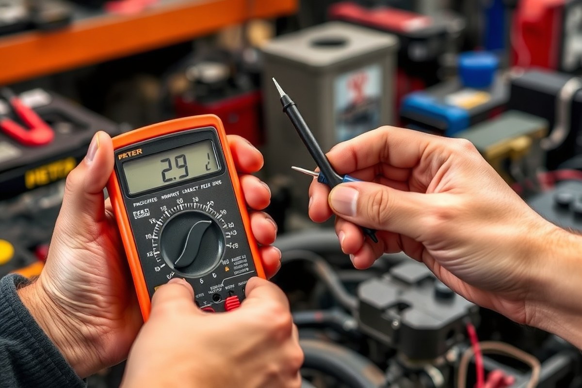
Testing a fuel sending unit with a digital multimeter involves measuring resistance to verify the unit’s condition and ensure it responds logically as the float arm moves. Resistance changes in the fuel sending unit correspond directly to the fuel level inside the tank, making these measurements important for diagnosing fuel gauge problems. This test requires removing the sending unit from the fuel tank for accurate results, especially to observe resistance changes across the float arm’s travel.
Set your digital multimeter to the ohms (Ω) setting to measure resistance, or to DC volts if checking whether the sending unit receives the proper voltage from the gauge circuit. Pay attention to the manufacturer’s resistance specifications for your specific vehicle since typical resistance can range between 0 to about 90 ohms but varies by model. Inconsistent or infinite resistance readings usually indicate a broken resistor or wiring issues inside the sending unit.
- Prepare the multimeter: Turn on your digital multimeter and set it to measure resistance (ohms, Ω). For voltage tests, switch to the DC voltage setting, typically the 20V scale.
- Access the fuel sending unit: Remove the fuel sending unit from the fuel tank following safe vehicle procedures to avoid fuel spillage or ignition risk.
- Connect multimeter leads: Attach the multimeter probes to the sending unit terminals. For a two-wire sending unit, connect to both wires; for three-wire units, consult wiring diagrams for correct terminals.
- Gently maneuver the float arm throughout its entire travel while observing the multimeter’s resistance changes. The resistance should vary consistently with no sudden spikes or falls.
- Observe and record resistance values: Note where the resistance starts (empty tank) and where it ends (full tank). Compare these values with manufacturer specs to identify if the unit reading is within acceptable range.
- Check for erratic or infinite readings: If resistance is unstable or shows infinity, the sending unit may have a broken wire or faulty resistor inside and likely needs replacement.
- Test voltage (optional): To confirm the sending unit gets proper voltage, place the multimeter on the DC volts setting. Connect the positive lead to the sending unit wire and the negative lead to ground. Turn the ignition to the “on” position without starting the engine and verify a reading up to about 12 volts, depending on vehicle system voltage.
- Compare and decide: Use your findings to determine if the sending unit is functioning properly. Consistent resistance changes aligned with fuel level mean a good sending unit. Erratic or out-of-spec results warrant repair or replacement.
Recognizing Symptoms of a Faulty Fuel Sending Unit

A faulty fuel sending unit often manifests through noticeable symptoms that impact the accuracy of your fuel gauge and, in some cases, the performance of your engine. The main role of the sending unit is to relay the correct fuel level to the dashboard gauge. When it fails, you get unreliable readings which sometimes leads to running out of fuel unexpectedly or the engine stalling.
Common symptoms include the fuel gauge needle sticking at full or empty despite real fuel changes, or erratic gauge movement like bouncing or jumping randomly. Erratic needle behavior typically points to worn internal components of the sending unit, such as the rheostat track. A stuck float inside the unit can cause the gauge to constantly display full or empty. Sometimes electrical issues like corrosion or a short circuit in the wiring cause these problems, and they mimic a faulty sending unit.
- Fuel gauge permanently reads empty or full regardless of actual fuel level.
- Needle bounces or moves unpredictably when driving or with ignition on.
- Engine stalls or hesitates due to incorrect fuel level feedback and disrupted fuel delivery.
- Check engine light flickers without other clear fault.
- Fuel gauge shows rapid fluctuations after refueling.
- Electrical faults such as blown fuses or corroded ground points nearby.
Issues with the fuel sending unit can indeed cause engine problems. Incorrect fuel level signals might trick the fuel pump controller or ECU into adjusting delivery improperly, resulting in stalls or hesitation. If the gauge reads empty constantly, suspect a blown fuse or a punctured float. A gauge that always reads full often relates to a broken ground wire or poor chassis ground connection.
Diagnosing a faulty fuel sending unit starts with observing these symptoms closely. The erratic behavior of the fuel gauge is a key indicator that the rheostat or float inside the sending unit is worn or stuck. Constant empty or full reads more likely point to wiring or fuse faults. Watching how the fuel gauge responds when the ignition is on can help narrow down the issue before proceeding to resistance checks or removing the unit for inspection.
Always check the fuse and ground connections first before replacing the fuel sending unit to avoid unnecessary parts costs and labor.
Safe Access and Removal of the Fuel Sending Unit
Accessing and removing the fuel sending unit safely requires careful preparation to avoid fuel spills, fire hazards, and damage to the unit or fuel tank. The unit is commonly found beneath the rear seat or trunk behind an access panel. Following the exact steps for your vehicle and taking proper safety measures will help ensure a smooth and secure removal process.
Locating the Fuel Sending Unit Access Panel
The fuel sending unit is usually mounted inside the fuel tank and is accessed through a panel located under the rear seat or in the trunk. Some vehicles have a removable panel specifically designed for this purpose, avoiding the need to drop the fuel tank. Without an access panel, you will need to lower the fuel tank, which is more involved and risky.
Consult your vehicle’s repair manual to find the precise location of the access panel. Many models include screws or bolts securing a cover plate that you can remove to reach the sending unit. Ensuring you have identified the correct panel is essential to prevent unnecessary work or damage.
Preparing Safety Equipment and Precautions
Working around fuel requires strict safety protocols. Always perform the work in a well-ventilated area away from open flames, sparks, or ignition sources. Disconnect the negative terminal of the vehicle’s battery before starting to reduce electrical hazards.
Drain the fuel tank partially to reduce weight and minimize fuel spillage when removing the sending unit. Use a proper container and approved pump or siphoning tool designed for fuel removal. Wear gloves and safety glasses to protect skin and eyes from fuel exposure. Make sure the area around the sending unit is clean and dry to prevent dirt from entering the fuel tank.
Steps to Remove the Sending Unit
Follow these methodical steps to remove the fuel sending unit without damage. Have basic hand tools on hand, such as screwdrivers, socket wrenches, and pliers, as well as replacement gaskets or O-rings, which are often required during reinstallation.
- Park the vehicle on a flat surface and ensure the engine is cool to reduce fire risk.
- Disconnect the negative battery cable to disable the electrical system.
- Drain some fuel from the tank to lower the fuel level below the sending unit.
- Remove the rear seat or trunk liner to expose the access panel covering the sending unit.
- Unscrew or unbolt the access panel carefully, avoiding damage to the surrounding area.
- Disconnect the electrical connector and any fuel lines attached to the sending unit, catching spilled fuel with a rag or container.
- Unscrew or unbolt the sending unit from the fuel tank, noting how it’s positioned for reinstallation.
- Lift the sending unit out of the fuel tank slowly, keeping the float arm clear to prevent bending.
Replacing the gasket or O-ring during reinstall is critical to prevent leaks. Vehicles without an access panel will require dropping the fuel tank after relieving fuel system pressure, which involves additional steps and precautions found in the repair manual. Neglecting these steps can lead to damage or fuel leaks.
Understanding Resistance Ranges and Fuel Level Correlation
Fuel sending units operate as variable resistors, adjusting resistance based on the float mechanism’s position inside your fuel tank. Understanding these resistance ranges is key to diagnosing whether the unit accurately reflects fuel levels. Typically, resistance is highest when the tank is empty and lowest when full, but exact values depend on the vehicle manufacturer.
Automakers provide specifications for resistance values at different fuel levels, often found in the vehicle’s service manual or technical specification sheets. To measure resistance effectively, connect your multimeter leads to the sending unit’s two terminals, then slowly move the float arm from empty to full. Watch for a smooth change in resistance corresponding to the fuel level indicated in your manual or spec sheet.
| Manufacturer | Resistance at Empty (Ohms) | Resistance at Full (Ohms) |
|---|---|---|
| Volkswagen (Typical stock) | 73 ± 2 | 10 ± 2 |
| Ford (Typical stock) | 73 | 10 |
Resistance measurements outside these ranges or erratic readings often signal a faulty sending unit. For example, if the resistance remains constant despite moving the float arm, the variable resistor inside the unit may be damaged or the float mechanism could be stuck or broken. This lack of change means the sending unit cannot accurately detect fuel level changes, and replacement is usually necessary.
When verifying your unit, expect a gradual, consistent resistance shift from the high-ohm reading at empty to the low-ohm reading at full. If your fuel sending unit readings are way out of spec, repairing or replacing it is the best way to restore accurate fuel level readings and avoid surprises at the pump. Always consult your vehicle’s manual or manufacturer specs for precise resistance values, since these can vary. Checking resistance against the correct values ensures the sending unit’s health and precise interaction with your fuel gauge system.
Testing Differences Between 2-wire and 3-wire Sending Units
Testing fuel sending units depends on whether your unit uses two or three wires. Two-wire units have a simpler wiring setup, typically ground and signal, while three-wire units add a power wire, which requires identifying each wire correctly before testing. Correctly wiring your multimeter is essential to get accurate resistance or voltage readings and avoid damage to the unit.
Identifying Wire Functions on 3-wire Units
Three-wire fuel sending units consist of a ground wire, a power wire (usually 12 volts from the ignition), and a signal wire that sends the fuel level information to the gauge. Before testing, trace each wire from the sending unit connector to the fuel gauge and vehicle power source to confirm their roles. The power wire provides voltage to the sending unit’s resistor circuit, the ground wire completes the circuit, and the signal wire carries the variable voltage or resistance back to the gauge.
You can often identify wires by color coding or by consulting a wiring diagram specific to your vehicle’s make and model. Testing continuity to ground or voltage presence with your multimeter can also confirm wire functions. The ground wire should show continuity to vehicle chassis ground, and the power wire should show around 12 volts when the ignition is on.
Multimeter Setup for 2-wire Units
Two-wire sending units typically combine the ground and signal functions into two terminals: one wire connects to ground, and the other is the signal wire running to the fuel gauge. For accurate resistance testing, set your multimeter to the ohms (Ω) setting.
Before you begin, ensure the vehicle ignition is off to prevent electrical damage. Disconnect the sending unit connector and clean the terminals if necessary to get a good reading. Connect the multimeter’s black (negative) lead to the sending unit’s ground terminal, which may be the casing itself or a dedicated ground wire. Connect the red (positive) lead to the signal wire terminal. This setup lets you measure the resistance that changes with fuel level.
Performing the Resistance and Voltage Tests
Testing the fuel sending unit involves measuring resistance for both 2-wire and 3-wire units, and optionally voltage for 3-wire units. Start with resistance testing because it directly verifies the variable resistor’s condition inside the sending unit. Resistance values vary depending on fuel level; an empty tank often reads high ohms (several hundred to thousands), while a full tank reads low ohms (tens to low hundreds). For 2-wire units:
- Turn off the vehicle and disconnect the fuel sending unit wiring harness.
- Set your multimeter to measure resistance (ohms).
- Connect the negative multimeter lead to the sending unit’s ground terminal.
- Connect the positive lead to the sending unit’s signal terminal.
- Move the fuel float manually if accessible to see resistance change.
- Compare the readings to your vehicle’s service manual for acceptable resistance ranges.
- Look for a smooth resistance change; jumps or no change indicates a fault.
For 3-wire units, add a voltage test:
- With the vehicle ignition switched on, use the multimeter on the voltage setting.
- Measure voltage between the power wire and ground to verify a steady 12 volts supply.
- Measure voltage on the signal wire against ground while moving the float; voltage should vary smoothly corresponding to fuel level.
Warning: Avoid applying voltage directly to the sending unit terminals without proper setup; excessive voltage can damage the unit. Always keep ignition off when connecting or disconnecting harnesses unless performing a live voltage test.
Troubleshooting Common Testing Issues and Mistakes
Common mistakes during fuel sending unit testing often lead to confusing or incorrect results. One frequent error occurs when the unit is tested while tilted or sideways. This position changes how the float presses against the resistance sensor, causing readings that jump, stick, or move erratically. Holding the unit flat and steady during testing prevents false readings and mimics the actual position inside the tank.
Another recurring issue arises from wiring faults. Even if the fuel sending unit shows correct Ohm values during testing, wiring problems can deliver no or wrong signals to the dashboard gauge. The wiring harness between the sending unit and the fuel gauge is complex and sensitive to breaks, corrosion, or loose connections. When your fuel gauge needle doesn’t move as it should, first check the wiring continuity and grounding before deciding the sending unit is faulty. A lack of proper grounding causes no continuity and inaccurate readings, which often gets misdiagnosed.
Erratic readings or no change during testing can also result from poor contacts inside the sending unit itself. Corroded or worn contacts on the float arm might cause the resistance to fluctuate. Minor repairs like cleaning contacts or replacing a worn float can restore proper function, although replacement is often more reliable in the long run.
- Always test the sending unit flat, mimicking its in-tank position, to avoid pressure changes affecting readings.
- Verify wiring harness continuity and ground connections before replacing the sending unit.
- Look for corrosion or worn contacts on the float arm; clean or lightly sand contacts to improve readings.
- Check for erratic gauge needle movement that may indicate wiring issues rather than sending unit failure.
- Ensure all connectors and terminals between the sending unit and dashboard are tight and free of damage.
- Use a quality multimeter calibrated for resistance to avoid inaccurate Ohm readings.
Fixing inaccurate or unstable readings involves a systematic approach: first, secure the sending unit in the correct testing position, then inspect wiring and connections. Confirm the sending unit is correctly grounded and wired; if readings still jump around, inspect internal mechanical parts such as the float. The dashboard gauge itself might cause false readings if it is malfunctioning or if its internal circuitry isn’t receiving accurate input from the sender. Since the fuel gauge display and sending unit form a closed loop involving wiring and internal electronics, narrowing down the fault requires testing each link carefully.
Replacing the entire fuel sending unit is often cost-effective and reduces guesswork. Repair attempts on worn or corroded parts can work short term but risk recurring problems. Paying $50 to $150 for a new sending unit saves time compared to troubleshooting wiring for hours and prevents intermittent fuel gauge issues on the road. Remember that properly identifying the actual fault saves both money and frustration.
When to Replace or Repair a Fuel Sending Unit
A fuel sending unit can sometimes be repaired, but replacement is often the more reliable solution. Repairing an internal component like the float arm or resistor strip may work temporarily, but the enclosed mechanism is delicate and prone to wear. Testing that reveals inconsistent resistance readings or erratic fuel gauge actions, like sudden jumps or no movement, likely points to a unit that needs replacing. Consistent continuity and smooth resistance changes usually indicate the unit is functioning properly and does not require a new part.
The lifespan of a fuel sending unit varies widely, typically lasting between 5 to 15 years depending largely on fuel quality, exposure to contaminants, frequency of tank emptying, and environmental conditions like heat and moisture. Dirty or low-quality fuel accelerates corrosion and mechanical wear inside the unit, shortening its service life. Vehicles frequently driven in dusty or humid climates also experience faster degradation. There’s no rigid replacement interval, so monitoring symptoms and testing performance are key.
Signs confirming the need for replacement include inaccurate fuel gauge readings that do not match actual fuel levels, a gauge needle stuck at full or empty, or fluctuating readings when the vehicle is idling or in motion. A sending unit that fails resistance tests, showing continuity drops, open circuits, or resistance values outside the specifications in your vehicle’s repair manual, should be replaced to restore accurate fuel measurement. Erratic gauge behavior despite a working gauge cluster also signals a unit problem.
To decide on replace versus repair, begin by carefully measuring resistance with a multimeter across the unit’s terminals while moving the float arm slowly through its full range. Resistance that shifts smoothly within the specified range (typically around 10 to 90 ohms, but check your manual) indicates the unit is still working. Any noticeable jumps, drops to zero, or open readings call for replacement. Attempting to clean or realign the float arm can be a short-term fix but rarely restores full reliability.
Replacing a fuel sending unit often requires lowering the fuel tank, which can be labor-intensive and require safety precautions to handle residual fuel safely. The replacement part should match the original in resistance range and wiring configuration to ensure proper gauge function. Installing the part into a clean tank free of debris prevents premature damage. Costs range from about $50 to $200 for the sending unit depending on the vehicle make and model, with labor adding more if a professional mechanic is involved.
Use this checklist to decide on replacement: Has testing shown smooth resistance changes? Are the gauge readings erratic or stuck? Is the fuel level indication consistently inaccurate? Has the unit been in service for over a decade under harsh conditions? Answering yes to any of these questions means replacement offers a safer and more reliable option. Repair attempts are usually limited to external adjustments or cleaning, offering only a chance for a temporary fix rather than a lasting solution.
Confirming Accuracy After Testing and Installation
Confirming the accuracy of a fuel sending unit after installation is essential to ensure the fuel gauge displays the correct fuel level. This process includes bench testing the sending unit, reinstalling it carefully, and calibrating the fuel gauge if needed. Accurate readings help avoid running out of fuel unexpectedly or misjudging your vehicle’s fuel status.
Performing a Bench Test of the Sending Unit
Before reinstalling the sending unit, bench testing can confirm it functions correctly and outputs the proper voltage range corresponding to fuel levels. This step saves time and effort by catching faulty units early.
- Connect a reliable power source, typically 12V, to the sending unit’s positive terminal.
- Attach a multimeter to measure the output voltage from the sending unit’s signal wire to the ground.
- Manually move the float arm through its range to simulate fuel levels from empty to full.
- Record voltage readings at key float positions, expecting a steady increase or decrease consistent with the manufacturer’s specified voltage range.
- Verify the sending unit’s ground connection is solid; poor grounding can cause erratic readings.
Proper grounding during bench testing is important; a loose ground can produce false readings that lead to unnecessary replacement.
Reinstalling and Observing Fuel Gauge Behavior
After bench testing confirms the sending unit is operating within expected parameters, reinstall it carefully to avoid damaging wiring or the float arm. Once installed, observe the fuel gauge’s behavior with the ignition on to check if it responds accurately.
- Secure the sending unit in the fuel tank, ensuring the float moves freely and the unit is properly sealed.
- Reconnect all electrical connectors and ensure good grounding both at the sending unit and the gauge.
- Turn the ignition key to the “on” position without starting the engine.
- Watch the fuel gauge needle for smooth movement corresponding to the actual fuel level or the float arm position.
- Note any jumps, stalls, or incorrect readings that suggest installation or wiring issues.
Check the installation for loose connectors or pinched wires if the gauge behaves erratically or sticks at one position.
Gauge Calibration and Final Verification
Calibrating the fuel gauge may be necessary after installing a new sending unit, especially if the sending unit has a different resistance range than the original. Most gauges have a “Zero” adjustment lever or screw behind the gauge face for fine-tuning.
- Locate the “Zero” adjustment lever behind the fuel gauge panel.
- Set the sending unit float to the empty position or simulate empty by grounding the signal wire as per your vehicle’s wiring diagram.
- Adjust the “Zero” lever so the fuel gauge needle rests exactly on the empty mark.
- Repeat with the float at the full position, ensuring the gauge reads full correctly.
- Cycle through intermediate float positions to confirm the gauge needle moves smoothly and corresponds well with fuel level.
- Drive the vehicle for a short distance to verify the gauge stays accurate under real conditions.
Adjustments should be minimal; large corrections might indicate an incompatible sending unit or wiring problem requiring professional inspection.
Step-by-Step Action Plan to Test Your Fuel Sending Unit
Follow these clear steps to test your fuel sending unit and confirm its accuracy in reporting fuel levels.
- Before you start: Gather a digital multimeter, safety gear, and your vehicle’s service manual to reference the correct resistance ranges for your sending unit. Knowing the specs helps you identify faults accurately.
- Day 1 – Access the unit: Safely disconnect the battery and remove the fuel tank or access panel according to your vehicle’s instructions. You’ll know you did it right when you reach the sending unit without damaging fuel lines or electrical connections.
- Day 1 – Visual inspection: Check for corrosion, loose wires, or physical damage on the sending unit. Clear signs of wear indicate a likely need for replacement.
- Day 1 – Measure resistance: Using the multimeter, test the sending unit terminals at various float positions. Resistance values should match your manual’s fuel level chart; consistent mismatches signal a faulty unit.
- Day 1 – Reconnect and test gauge: Temporarily reconnect the unit and observe the dashboard fuel gauge movement. Proper response confirms a functioning sending unit.
- Day 2 – Reinstall securely: After confirming functionality, reinstall the sending unit and fuel tank according to safety guidelines. A secure fit will prevent leaks and inaccurate readings.
- Day 3 – Road test: Drive the vehicle and watch the fuel gauge respond to changes in fuel level. Smooth, logical gauge movement means your repair is successful.
Frequently Asked Questions
What Tools Do I Need to Test a Fuel Sending Unit?
You need a digital multimeter, basic hand tools for removal, and sometimes a wiring diagram. A multimeter helps measure resistance and voltage critical to diagnosing the sending unit’s function.
Can I Test the Fuel Sending Unit Without Removing It from the Fuel Tank?
Yes, testing is possible by accessing the wiring and measuring resistance or voltage, but removal allows more accurate readings by moving the float arm.
How Do I Identify the Correct Wires on a 3-wire Fuel Sending Unit?
Locate power, ground, and signal wires using a wiring diagram or multimeter for voltage presence and continuity tests. Correct wire ID is important for accurate testing.
What Range of Resistance Should I Expect in a Fuel Sending Unit?
Resistance usually varies from about 0 to 90 Ohms as the fuel level changes; check your specific vehicle’s specs. This range helps correlate resistance to fuel level.
How Can I Confirm If My Fuel Gauge or Sending Unit Is Faulty?
Conduct a 10-minute ground bypass test to determine if the dashboard gauge or sending unit is at fault. This isolates the problem quickly without full disassembly.
Is It Safe to Use a Fuel Sending Unit That Tests at the Extreme End of Resistance Ranges?
Generally, yes, as new units can test from 0 to 90 Ohms and still operate properly after calibration. Check for smooth resistance changes rather than fixed extremes.
Final Thoughts
Testing your fuel sending unit gives you a reliable way to diagnose inaccurate fuel readings before investing in costly repairs. Focus on matching resistance values to your vehicle’s specifications for the most precise diagnosis. Start by safely accessing the unit and methodically measuring its electrical resistance at different float positions. Taking these steps ensures you restore accurate fuel gauge readings and avoid running unexpectedly out of fuel.