
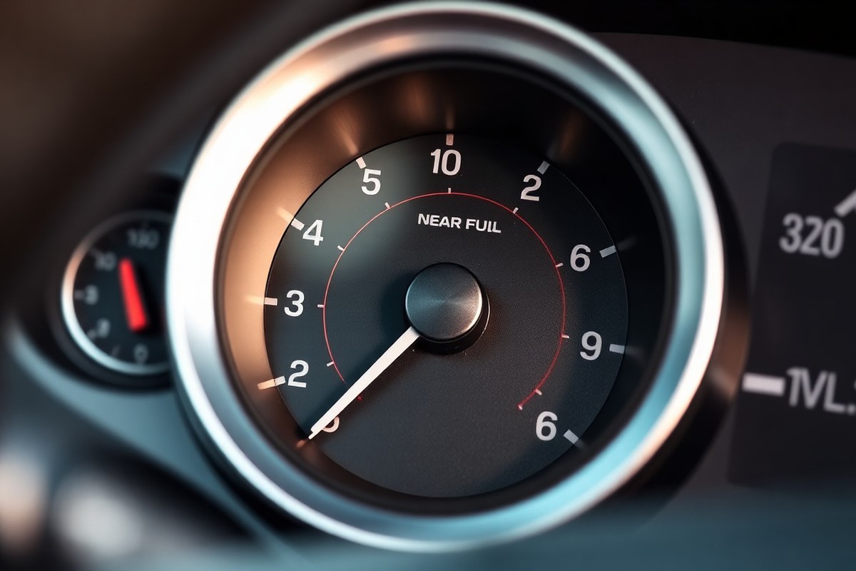
How Do Fuel Gauges Work: A Complete Guide to Their Operation and Types
Fuel gauges measure fuel level using a sending unit inside the tank connected to a gauge on the dashboard. The sending unit has a float that moves with the fuel level, adjusting electrical resistance that controls the gauge needle’s position. This system converts the physical level of fuel into an easy-to-read display, helping you monitor fuel without opening the tank.
This explanation suits car owners, automotive enthusiasts, and DIY mechanics interested in understanding how fuel gauges work, how they differ, and how to handle common issues. You’ll learn about the main parts, why gauges can be inaccurate, types of fuel gauges, and tips for diagnosing problems safely.
Key Takeaways
- A fuel gauge system includes a float, an armature, and two coils spaced 90° apart to measure fuel level accurately.
- Fuel sending units vary by make and can cost between $50 and $800 including labor to replace.
- Fuel gauges often show empty when fuel remains and full for roughly the first 50 miles due to calibration quirks.
- Check wiring connections at the back of the fuel gauge when diagnosing gauge inaccuracies.
- Replacing a blown fuse costs $10 to $20 on average; specialty fuses can cost up to $100.
- If resistance tests show no connection, remove and test the fuel sending unit for faults.
How Does a Fuel Gauge Measure Fuel Level?

A fuel gauge measures the fuel level in a vehicle by using a sending unit inside the tank that changes its electrical resistance based on the fuel amount. The sending unit consists of a float attached to an arm that moves up and down with the fuel level. This arm adjusts a variable resistor, often called a rheostat, inside the tank. As the float moves, the resistance value changes, affecting the electric current flowing through the circuit connected to the dashboard gauge.
The float is designed to float on the surface of the fuel in the tank, allowing it to rise when the tank is full and drop when the fuel level decreases. The arm linked to the float moves a contact along a coil of resistance wire. When the float is at the top, indicating a full tank, the resistance is at its minimum, usually around 30 ohms. When the float is at the bottom, indicating empty, the resistance reaches much higher values, such as 240 ohms. This resistance range varies slightly depending on the vehicle and sending unit design.
The change in resistance alters the current passing through the circuit when the vehicle’s ignition is turned on. The dashboard fuel gauge uses this current to move its needle via a bimetallic strip mechanism or another indicator system. In a common analog fuel gauge, the incoming current heats a bimetallic strip, causing it to bend and move the needle across the dial to show the fuel level. Higher current, caused by low resistance when the tank is full, moves the needle toward “Full.” Lower current from higher resistance when the tank is near empty makes the needle move toward “Empty.”
This setup works because the fuel sending unit and the dashboard gauge form one complete electrical circuit. The sending unit inside the tank constantly communicates the fuel level by adjusting resistance. The gauge on the dashboard receives this signal and converts it into a visual reading. This direct relationship means the float’s position inside the tank ultimately determines the needle’s position on the dash.
Variations exist depending on vehicle make and model, but the key principle remains the same: a float moves a variable resistor, changing electrical resistance to send a signal. This signal controls the dashboard gauge’s needle, indicating fuel level. Problems in this system typically occur when the sending unit’s arm or float gets stuck, the resistor wears out, or wiring issues cause signal loss, leading to inaccurate fuel readings.
Main Components of a Vehicle Fuel Gauge System

The main components of a vehicle fuel gauge system work together to measure and display the fuel level in the tank accurately. The sending unit inside the tank detects fuel level through a float and resistance mechanism, while the dashboard gauge interprets this information to show the driver how much fuel remains. Additional parts like coils and rheostats regulate electrical signals that translate changes in fuel level into readable gauge movements.
Fuel Sending Unit and Float Mechanism
The sending unit, located inside the fuel tank, is the component responsible for sensing the actual fuel level. It includes a float, a buoyant device that rises and falls with the fuel, and an arm connected to a variable resistor called a potentiometer or rheostat. As the fuel level changes, the float moves, adjusting the position of the arm on the potentiometer. This movement changes the electrical resistance in the circuit, which corresponds directly to the fuel level.
This system provides a continuous signal rather than fixed points, allowing for smooth gauge movement. The float is usually made of plastic or metal sealed to resist fuel exposure and corrosion. Over time, the float or arm can wear out or become stuck, leading to inaccurate readings or a static fuel gauge. To inspect the sending unit, you disconnect its wiring and check whether the resistance changes as the float moves through the expected range.
Dashboard Fuel Gauge and Needle Assembly
The dashboard fuel gauge serves as the visible feedback mechanism for the driver. It contains a coil, an armature, and a pointer that moves across a calibrated dial to indicate fuel level. Generally, two electromagnetic coils spaced at 90 degrees work with the pointer to convert electrical signals into physical movement. When electrical current varies due to resistance changes from the sending unit, the magnetic field affects the position of the pointer.
This setup is designed to respond smoothly, so the needle deflects proportionally to the fuel level while minimizing sudden jumps or sticking. The gauge assembly must be calibrated carefully during manufacturing to match the tank’s capacity and sensor characteristics. A malfunctioning coil, damaged pointer, or loss of magnetic force can cause the gauge to stick or show empty/full inaccurately.
Electrical Wiring and Resistance Rheostat
The electrical wiring links the sending unit inside the tank with the fuel gauge on the dashboard. The system typically uses the vehicle’s battery voltage to send signals through the fuel sender’s variable resistor. When fuel level changes, the rheostat’s resistance changes accordingly, which adjusts the current flowing to the gauge. This change in electrical current moves the gauge needle to reflect the new fuel level.
Key to this working properly is a secure ground connection, clean wiring, and intact connectors. Corrosion, loose connections, or damaged wires can cause the gauge to read incorrectly or not respond at all. Testing the circuit involves checking for voltage at the sending unit, ensuring there is resistance that changes with float movement, and verifying continuity in the wiring.
- Check for consistent voltage supply from the battery to the gauge circuit
- Measure resistance changes in the sending unit as the float moves
- Inspect electrical connectors for corrosion or looseness
- Ensure grounding points are clean and tight
- Test gauge needle movement manually if feasible
Faults here often mimic sending unit problems, making electrical testing essential before replacing parts.
Always disconnect the battery before working on the fuel gauge wiring to prevent short circuits or sparks near flammable fuel vapors.
Additional Components in Modern Gauges
More recent fuel gauge systems may include extra components like multiple tank units, telematic control units, and GPS tracking to improve accuracy and data reporting. Some use magnetic-type gauges with small electromagnets that improve sensitivity and response time. These advanced systems still rely on the fundamental sending unit and gauge setup but add electronic processing to monitor and transmit fuel level data more precisely.
Vehicles with dual tanks have two sending units linked to a central dashboard gauge that averages or switches between tanks automatically. Some models may also include indicators or alarm signals when the fuel reaches a critical low level. Overall, these components aim to improve driver information and reduce false readings common in simpler systems.
Types of Fuel Gauges and How They Differ
Fuel gauges in vehicles mainly fall into three categories: mechanical, electrical (often analog), and digital. Each type measures fuel differently and suits specific vehicle designs and driver needs. Mechanical gauges use physical linkages connected to a float in the tank to move a needle on the dashboard. Electrical gauges rely on sending units that vary resistance or current according to the float level, with the dashboard needle responding accordingly. Digital gauges convert these signals into electronic displays showing fuel quantity in bars or percentages.
Mechanical gauges are straightforward, typically cheaper and easier to repair. However, they offer lower precision and are less common in modern vehicles. Electrical analog gauges provide more accuracy and smoother needle movement but depend on well-functioning sending units and wiring. Digital gauges present fuel levels clearly and often integrate with vehicle computer systems, delivering real-time and precise information. They usually come at a higher cost and may complicate DIY repairs due to electronic complexity. Below is a comparison table summarizing key differences and usage contexts of these fuel gauge types:
| Type | How It Works | Pros | Cons | Common Usage |
|---|---|---|---|---|
| Mechanical | Float physically moves needle via linkages | Simple; low cost; easy to fix | Less precise; affected by wear over time | Vintage and classic cars; some motorcycles |
| Electrical (Analog) | Variable resistance or current controls needle position | Accurate; smooth needle movement; widely used | Requires wiring; susceptible to electrical faults | Most conventional cars and trucks pre-2000s |
| Digital | Electronic sensor signals displayed as bars or percentage | Precise; clearer readings; integrates with vehicle computers | More expensive; complex for DIY repairs | Modern cars and SUVs; vehicles with digital instrument clusters |
Analog fuel gauges, either mechanical or electrical, use a needle moving across a marked dial to show fuel level. Digital gauges replace the needle with numeric or bar graph displays. This difference is mainly in how the fuel level is communicated to you rather than the sensing method inside the tank. Digital systems usually rely on electrical sensors but convert readings for digital presentation. Choosing between them depends on your vehicle’s age, budget for maintenance, and the clarity of information you want while driving.
Why Fuel Gauges Can Be Inaccurate or Misleading
Fuel gauges often provide a general indication rather than precise measurement, which can lead to inaccuracies. The irregular shape of fuel tanks affects this because many tanks have curved or uneven surfaces. The float inside the tank moves with the fuel level but does not always correspond linearly due to these shapes, causing the gauge reading to jump or pause unexpectedly. Manufacturers sometimes adjust the gauge movement by using a calibration curve to approximate the fuel level relative to the float’s position, but this compensation is never perfect.
The vehicle’s angle and movement also play a significant role. Driving on hills, rough terrain, or during sharp turns causes the fuel to slosh within the tank, pushing the float up or down unpredictably. This movement can cause the fuel gauge needle or digital display to fluctuate momentarily, giving you a misleading sense of how much fuel remains. Such variations tend to settle when the vehicle is on level ground, but if you frequently drive in hilly or uneven areas, you may notice consistent oscillations in the gauge.
Electrical faults within the sender or wiring can create false readings of the fuel level. The sender unit in the tank, connected to a float, converts the float’s position into an electrical signal sent to the dashboard gauge. Any corrosion, damaged wiring, or poor grounding in this circuit can cause the gauge to behave erratically, show a dead fuel reading, or indicate a full tank inaccurately. Replacing a faulty fuse might cost around $10, while swapping out a sender unit and covering labor could reach up to $800, depending on your vehicle’s make and model.
Temperature changes impact fuel expansion and contraction, slightly affecting gauge accuracy as well. Gasoline expands when warm and contracts when cool, altering the fuel level without changing the volume inside the tank. While this effect is small and typically negligible for most drivers, it can matter in extreme climates or when precise fuel measurement is necessary. Terrain also influences how the sender and gauge behave since steep inclines tilt the fuel, shifting the float position and causing temporary reading errors.
The type of sensor used in the fuel gauge system also affects accuracy. Some fuel gauges use bimetallic strips or resistance sensors, with bimetallic types generally providing more precise readings. However, sensor wear over time can degrade this accuracy, and cheaper gauges might be less reliable. Understanding these limitations helps you interpret the fuel gauge readings more cautiously and avoid running unexpectedly low on fuel.
How to Diagnose a Faulty Fuel Gauge or Sending Unit
To diagnose a faulty fuel gauge or sending unit, you need to systematically check the fuse and wiring, measure the resistance of the sending unit, and test the dashboard gauge’s response. These steps help identify whether the problem lies in the wiring, fuse, sending unit, or gauge itself. Using a multimeter is essential for accurate measurements throughout the process.
Check Vehicle Fuse and Wiring Connections
Start by verifying the condition of the fuse related to the fuel gauge circuit and inspecting wiring connections for continuity and damage. Faulty wiring or a blown fuse can disrupt the power supply to the sending unit or gauge, causing erroneous readings or complete failure.
Use the vehicle’s owner or service manual to locate the fuel gauge fuse and wiring connectors. With the ignition switched on, test the fuse for continuity and measure voltage at the fuse holder and wiring harness. Make sure connectors have a firm and corrosion-free connection.
- Locate the fuel gauge fuse using the fuse box diagram in the owner’s manual.
- Remove the fuse and check it visually for a break or use a multimeter to test continuity.
- Turn on the ignition without starting the engine and measure voltage at the fuse socket; it should read about 12 volts.
- Inspect wiring running from the fuse to the sending unit and gauge for breaks, fraying, or corrosion.
- Check the grounding wire on the sending unit; a poor ground can cause the gauge to act erratically.
- Reconnect any loose or corroded terminals, or replace damaged wiring as needed.
Always disconnect the battery before working on wiring connections to prevent short circuits or shocks.
Measure Sending Unit Resistance Values
The sending unit’s resistance changes according to the fuel level and affects the gauge reading. Measuring this resistance while moving the float arm helps determine if the sender works correctly. Consult the service manual for the specific resistance range, which usually spans from about 10 ohms (full) to 90 ohms (empty) but varies by model.
Testing requires removing the sending unit or accessing its wiring harness, then using a multimeter set to measure resistance. Moving the float arm should cause a smooth change in resistance; erratic readings indicate a faulty sending unit.
- Turn off the ignition and disconnect the sending unit’s wiring connector.
- Set your multimeter to the ohms (Ω) scale appropriate for the expected resistance range.
- Connect the multimeter leads to the sending unit terminals or wiring harness.
- Slowly move the float arm through its range from empty to full.
- Observe the resistance readings for smooth and continuous change within the expected range.
Intermittent or no change in resistance usually means the sending unit needs replacement.
Perform Dashboard Gauge Movement Test
Testing the dashboard gauge itself shows whether it responds properly to input from the sending unit or a simulated signal. This verifies gauge functionality independent of the sender or wiring. Some vehicles allow a test mode by turning the ignition on and off while observing gauge movement.
You can also use a jumper wire to simulate a grounded or powered signal on the sending unit wire, which should cause the gauge needle to move toward empty or full. Lack of response typically means the gauge or dashboard circuitry is faulty.
- Turn the ignition to the “on” position without starting the engine.
- Connect a jumper wire from the sending unit signal wire to ground; the gauge should move toward empty.
- Disconnect the jumper; the gauge should return to its previous reading.
- Connect the signal wire directly to a 12-volt source; the gauge should move toward full.
- Note any failure to move or erratic movement, which can indicate a defective gauge.
Refer to the wiring diagram for your vehicle before applying jumpers to avoid damaging electrical components.
Replace or Repair Based on Test Outcomes
After completing the tests, replace the faulty component depending on which test failed. Replace blown fuses or repair damaged wiring first, as these are the simplest fixes. If the sending unit does not vary resistance smoothly, swap it out with a compatible replacement.
A non-responsive or erratically moving gauge often requires professional repair or instrument cluster replacement. Repair costs vary: a fuel sending unit typically costs $50 to $150, while gauge repairs can be $100 to $300 or more depending on vehicle make and labor. DIY repairs are often limited to testing and replacing fuses and sending units.
- Repair or replace any blown fuse or damaged wiring identified during the inspection.
- Swap out a sending unit that failed resistance tests with a manufacturer-approved replacement.
- Seek professional calibration or replacement if the dashboard gauge does not respond correctly.
- Clear any trouble codes with an OBD-II scanner if applicable, then retest.
Always consult a licensed mechanic for instrument cluster repairs, as internal electronics require special tools and expertise.
Common Faults, Causes, and Practical Fixes
Fuel gauges can fail for several common reasons that lead to inaccurate or stuck readings. One frequent cause is a stuck or damaged float inside the gas tank. The float is responsible for moving along the fuel surface to measure the level. If it sticks due to debris or corrosion, the gauge needle may freeze on empty or full, inaccurately reflecting the available fuel.
Electrical faults within the gauge system also cause failures. An open circuit or wiring failure often results in the meter showing empty regardless of the actual fuel. This happens because the fuel gauge circuit is designed to default to empty to alert the driver early. Wiring shorts or damaged connectors disrupt the signal between the sending unit and the dashboard display.
Another point of failure is the fuel sending unit’s variable resistor, which changes resistance according to fuel level. With wear or corrosion, its resistance can become erratic or fixed, producing false readings. Thermostatic elements in some older electric gauges may also malfunction over time, skewing the output.
- Check fuse and wiring for continuity and damage, repairing or replacing faulty wires.
- Inspect the sending unit float for signs of sticking or wear; replace if necessary.
- Test the fuel sending unit resistor with a multimeter and substitute with a new unit if resistance values are off.
- Replace the fuel gauge on the instrument cluster when it fails to respond to corrected sending units.
- Clean connectors and terminal contacts to avoid poor electrical connections causing erratic readings.
Repair costs vary depending on the source of the issue. A wiring repair or fuse replacement typically ranges between $50 and $150, depending on labor involved. Replacing the sending unit usually costs $100 to $300, parts included. Fuel gauge replacement in the instrument cluster can be more expensive, from $200 to $500, as it may require partial dashboard disassembly. Prices also depend on vehicle make, model, and labor rates in your area.
Effective repairs result in the fuel gauge providing steady, accurate readings that match the actual fuel level in the tank. Poorly fixed issues may cause fluctuating indicators, sticking needles, or complete failure to register fuel levels. Regular inspection after repair helps ensure reliability before the gauge starts causing driver inconvenience or fuel mismanagement.
Safety Precautions When Working with Fuel Sending Units
Working with a fuel sending unit requires careful attention to safety because the unit is housed inside the fuel tank, where flammable vapors and liquids are present. Before you start any inspection or repair, disconnect the vehicle’s battery to eliminate the risk of sparks that could ignite fuel fumes. Ensure your workspace is well ventilated, away from open flames or heat sources. Avoid smoking or using tools that can generate sparks near the tank.
When accessing the sending unit, be mindful that fuel tanks may not be easy to reach and often require removing seats, trim panels, or even lowering the tank itself. This process can take several hours depending on the vehicle model. Wear protective gloves and safety goggles to guard against fuel splashes, which can irritate skin and eyes. Use containers approved for fuel storage to capture any spilled gasoline during removal or repairs. It is critical to wipe any fuel residue immediately to prevent slipping hazards and fire risks.
The electrical circuit connected to the sending unit should only be handled once you have confirmed all power is off. Use the proper tools recommended by the manufacturer to avoid damaging delicate wiring or connectors. Follow a step-by-step electrical test approach when diagnosing faults, as improper testing can short circuits or further damage the gauge system. This typically involves checking for continuity and resistance within specified ranges detailed in the vehicle’s service manual.
Fuel gauge repairs often involve replacing the sending unit, which can cost between $100 and $300 in parts, with labor varying widely depending on accessibility. Given the complexity and fire hazards, calling a professional mechanic is advised if you lack experience with fuel systems. Professionals have the proper equipment, such as non-sparking hand tools and ventilation setups, to safely complete the task. Attempting repairs without adequate knowledge or tools can lead to incorrectly installed units, increasing the risk of inaccurate fuel readings or leaks that compromise vehicle safety.
If you notice erratic fuel gauge behavior or suspect a sending unit failure, avoid continued DIY troubleshooting beyond simple external checks or gauge calibration resets. Fuel system components are sensitive, and mishandling can trigger fuel leaks or electrical shorts. Professionals can perform thorough diagnostics using specialized equipment, ensuring the sending unit and gauge function reliably without exposing you to risks.
Modern Advances in Fuel Gauge Technology
Modern fuel gauge systems use electronic technology combined with microprocessors to provide more accurate and responsive fuel level readings. These systems integrate sensors that detect the exact position of the fuel float arm and communicate this data digitally to the dashboard display and other vehicle systems. This approach improves precision, reduces signal noise from fuel movement, and enables the fuel data to support smart vehicle features.
Microprocessor-Controlled Fuel Gauges
Electronic fuel gauges now often include a microprocessor that processes input from advanced sensors. Instead of a simple variable resistor, these sensors sometimes use sealed detectors at the float arm pivot that detect a magnet’s angular position for precise fuel level detection. The microprocessor filters out errors caused by fuel sloshing, using software-based “anti-slosh” algorithms to stabilize the fuel level reading on the display. It converts the sensor’s analog signal into a digital output that controls the gauge readout.
The microprocessor continuously updates fuel level information several times per second to ensure the driver sees a smooth, stable fuel indicator. This results in improved accuracy compared to older analog fuel gauges, which often react sluggishly or fluctuate wildly. While a microprocessor-controlled fuel gauge costs more to manufacture and may require more complex repairs if faulty, the benefits include fewer false low-fuel warnings and a more reliable fuel status.
Fuel Level Sensors for Multiple Tanks
Vehicles equipped with multiple fuel tanks, such as RVs, trucks, or large SUVs, use separate fuel level sensors for each tank. Each sensor may operate similarly to those with sealed magnet detectors but is calibrated independently. The microprocessor system aggregates the data from all sensors and presents either the level for each individual tank or a combined total fuel level on the dashboard.
Integration with the vehicle’s onboard computer allows selection or scrolling between tanks or displays a unified readout. The gauge logic can alert the driver if one tank runs low before the other, preventing unexpected fuel starvation. Implementing multiple fuel sensors and the necessary electronics increases system complexity and cost. However, this setup provides better monitoring and management in vehicles that rely on multiple fuel sources.
Digital Display and Telemetry Integration
Fuel gauges with digital displays use LCD or LED screens to show the fuel level as a precise numeric value or a bar graph. Digital readouts offer clearer information than traditional needle gauges, removing ambiguity from interpreting gauge positions. These displays are often part of a cluster of instruments controlled by the vehicle’s microprocessor system.
Also, the same electronic fuel monitoring data integrates with telematics and fleet management systems for professional applications. Sensors used in fleet vehicles measure fuel levels accurately enough to detect small changes during refueling or fuel theft. This data streams continuously to fleet management software, allowing real-time tracking of fuel consumption and preventing losses.
Check your vehicle’s manual before attempting repairs on electronic fuel gauges, as high-tech sensors and microprocessors are sensitive and may require professional service.
Step-by-Step Action Plan to Check and Maintain Your Fuel Gauge
Follow this plan to keep your fuel gauge working accurately and spot problems early.
- Before you drive: Check the fuel gauge reading and compare it with the fuel level on the fuel cap or dipstick if available, to spot obvious issues.
- Day 1: Test the gauge by filling your tank fully, then observe the gauge to confirm it reads full or near full.
- Week 1: Monitor the gauge’s behavior during several drives to check for erratic or drifting readings.
- Week 2: Inspect the fuel sending unit wiring and connections for damage or corrosion, especially if you noticed issues earlier.
- Week 3: Use a multimeter to test the sending unit resistance if the gauge is still unreliable; refer to your vehicle’s service manual for specs.
- After your tests: Replace faulty sending units or gauges only if testing confirms a defect, or have a professional evaluate the system.
- Every oil change: Quickly check your fuel gauge as part of routine maintenance to catch future problems early.
Frequently Asked Questions
Can Fuel Gauges Work Accurately with Aftermarket Fuel Tanks?
Fuel gauges may struggle with aftermarket tanks due to shape and size differences affecting float movement. Recalibrating or replacing the sending unit often helps improve accuracy.
How Often Should You Test the Fuel Gauge System for Faults?
Testing fuel gauges yearly or during regular vehicle maintenance helps catch issues early. Regular checks prevent being stranded due to faulty readings.
Do Temperature Changes Affect How a Fuel Gauge Reads?
Temperature can slightly affect readings because fuel expands or contracts. Some advanced fuel gauges compensate for this to reduce errors.
Are Fuel Gauge Issues More Common in Older or Newer Vehicles?
Older vehicles tend to have more fuel gauge problems due to mechanical wear. Newer models use improved sensors and digital displays that reduce faults.
Is It Possible for a Full Tank to Show Empty on the Gauge?
Yes, a faulty sending unit or electrical connection can cause a full tank to show empty. Inspect wiring and float mechanism to fix this.
Can Sediment in the Fuel Tank Affect the Fuel Gauge?
Sediment can interfere with the float’s movement or damage the sending unit. Cleaning the tank during maintenance helps ensure accurate readings.
Final Thoughts
Your fuel gauge works by measuring changes in the fuel level through an electrical signal, but normal wear, wiring issues, or component failure can throw off its accuracy. Regular checks and timely repairs will help you rely on the gauge to avoid unexpected empty tanks. Start by observing how your fuel gauge reads after filling up, and address any irregularities promptly to maintain your vehicle’s performance and safety.